Как проще и быстрее исправить геометрию?
|
Автор |
Сообщение |
|
|---|---|---|
|
||
|
||
|
||
|
||
|
||
|
||
|
||
|
||
|
||
|


The Geometry rollout for patch objects contains most of the controls that let you alter the geometry of the patch, at either the Object (top) level, or one of the sub-object levels.
Interface
The controls on this rollout vary, depending on which level is active. If a control is not available for the active level, it might be grayed out or simply might not appear at all. The descriptions below indicate the levels at which controls are available.

Subdivision group (Vertex, Edge, Patch, and Element levels only)
- Bind (Vertex level only)
- Lets you create a seamless, gapless connection between two patch edges that have unequal numbers of vertices. The two patches must belong to the same object, and the vertex need not be selected first. Click Bind, then drag a line from an edge-based vertex (not a corner vertex) to the edge you want to bind it to. The cursor turns into a white cross when over a legal edge.

Binding patch edges
To exit Bind mode, click the Bind button again, or right-click in the active viewport.
Tip: When connecting two patches edge-to-edge, first line up as many pairs of vertices as possible, and use Weld to connect them. Then use Bind to connect the remaining vertices. Bound vertices cannot be manipulated directly, although their handles can.
Note: Bind is useful for connecting patch objects with different patch resolutions, such as a head and a neck, without the need to create additional patches in the lower-resolution object.
- Unbind (Vertex level only)
- Disconnects a vertex connected to a patch with Bind. Select the vertex, and then click Unbind.
- Subdivide (Edge, Patch, and Element levels only)
- Subdivides the selected sub-objects.
- Propagate When on, extends the subdivision to neighboring patches. Propagating the subdivisions along all contiguous patches prevents patch cracks where you have attached patches together.

Topology group
- Add Tri / Add Quad (Edge level only)
-
You can add Tri and Quad patches to any open edge of an object. On closed objects such as spheres, you can delete one or more existing patches to create open edges, and then add new patches.
The new patches adapt to the existing geometry. For example, when you add a patch to a curved edge, the new patch follows that curve and seamlessly extends it.

Original patch with edges selected (top) and three-sided patches added (bottom)
Add Tri adds a three-sided patch to each selected edge. Select one or more edges, then click Add Tri to add the patch or patches.
Add Quad adds a four-sided patch to each selected edge. Select one or more edges, and then click Add Quad to add the patch or patches.
- Create (Vertex, Patch, and Element levels only)
-
Lets you add geometry to the patch object. Available at Vertex, Patch, and Element sub-object levels only.
At the Vertex sub-object level, turn on Create and then click anywhere to add vertices to the object.
At the Patch and Element levels, you can add three- and four-sided patches. The cursor changes to white cross hairs when over an existing patch vertex. Select an existing vertex by clicking it. Click in free space to create a new vertex at that location; this vertex is included in the sequence of vertices for the new patch.
- To create a Tri Patch: Click three times in free space or on existing vertices. Right-click anywhere, or left-click one of the vertices in the current sequence to complete the creation of a Tri Patch.
- To create a Quad Patch: Click four times in free space or on existing vertices. The Quad Patch is automatically created at the fourth click.
No operation takes place if you right-click or select a vertex in the current sequence with only one or two vertices in the sequence.
- Detach (Patch and Element levels only)
-
Lets you select one or more patches or elements within the current object and then detach them (or copy them) to form a separate patch object.
- Reorient When on, the detached patch or element copies the position and orientation of the source object’s Local coordinate system (when the source object was created). The new detached object is moved and rotated so that its Local coordinate system is positioned and aligned with the origin of the current active grid.
- Copy When on, the detached patches or elements are copied to a new patch object, leaving the originals intact.
- Attach
-
Lets you attach an object to the currently selected patch object. Click the object you want to attach to the currently selected patch object.
If you attach a non-patch object, the object is converted to a patch object.
When you attach an object, the materials of the two objects are combined in the following way:
- If the object being attached does not have a material assigned, it inherits the material of the object it is being attached to.
- Likewise if the object you’re attaching to doesn’t have a material, it inherits the material of the object being attached.
- If both objects have materials, the resulting new material is a multi/sub-object material that encompasses the input materials. A dialog appears offering three methods of combining the objects’ materials and material IDs. For more information, see Attach Options Dialog.
Attach remains active in all sub-object modes, but always applies to objects.

Top: Original patch object with rendering
Bottom: Rendering with another patch attached
- Reorient
-
When on, reorients the attached element so that each patch’s creation local coordinate system is aligned with the creation local coordinate system of the selected patch.
- Delete (Vertex, Edge, Patch, and Element levels only)
-
Deletes the selected sub-objects.
Warning: Delete vertices or edges with caution. Deleting a vertex or edge also deletes the patches that share them. For example, if you delete the single vertex at the top of a spherical patch, the top four patches are also deleted.
- Break (Vertex and Edge levels only)
-
For vertices, breaks a vertex into multiple vertices. Use this if you need to split open an edge to add another patch or for general modeling operations. Select a vertex, and then click Break. After the break, select the individual vertices and move them to separate the edges.
For edges, splits an edge. Use this if you need to split open an edge for general modeling operations. Select one or more edges, and then click Break. After the break, move the handles of adjacent vertices to create a gap in the patch.
- Hide (Vertex, Edge, Patch, and Element levels only)
-
Hides the selected sub-objects. For vertices and edges, Hide also hides the patches that are attached to them.
Note: At least one patch in the object must remain visible.
- Unhide All
-
Restores any hidden sub-objects to visibility.


Weld group (Vertex and Edge levels only)
- Selected
-
Welds selected vertices that fall within the tolerance specified in the Weld Threshold spinner (to the right of the Weld button). Select the vertices you want to weld between two different patches, set the spinner to a sufficient distance, and click Selected.
At the Edge sub-object level, clicking Selected welds two edges that share vertices. You can use this to eliminate gaps on a surface.
- Target (Vertex level only)
-
Turn on and drag from one vertex to another to weld the vertices together. The dragged vertex fuses to the target vertex.
The pixels spinner to the right of the Target button sets the maximum distance in screen pixels between the mouse cursor and the target vertex.
Extrude & Bevel group (Edge, Patch, and Element levels only)
These controls let you extrude and bevel edges, patches, or elements. Extruding patches moves them along a normal and creates new patches that form the sides of the extrusion, connecting the selection to the object. Beveling adds a second step that lets you scale the extruded patches. You can extrude and bevel patches by dragging or by direct entry. You can also hold down the Shift key during extrusion, which creates a separate element.
Note: Sides created by beveling or extrusion are assigned to smoothing group 1.
- Extrude
-
Click this button, and then drag any edge, patch, or element to extrude it interactively. Hold down the Shift key during this operation to create a new element.
When the mouse cursor is over a selected patch or element, it changes to an Extrude cursor.
- Bevel (Patch and Element levels only)
-
Click this button, and then drag any patch or element to extrude it interactively, then click and release the mouse button, and drag again to bevel the extrusion. Hold down the Shift key during this operation to create a new element.
When the mouse cursor is over a selected element, it changes to a Bevel cursor.

Original patch (top) and inward and outward extrusions
Note: In some cases, particularly with closed objects (objects with no holes or open edges), the second bevel step might not produce visible results.
- Extrusion
-
This spinner sets whether the extrusion is outward or inward, depending on whether the value is positive or negative.
- Outlining (Patch and Element levels only)
-
This spinner lets you scale selected patches or elements bigger or smaller, depending on whether the value is positive or negative. It is normally used after an extrusion for beveling the extruded patches.
- Normal
-
If Normal is set to Local (the default), extrusion takes place along the normal of each selected edge, patch, or individual patch in an element. If normal is set to Group, extrusion takes place along the averaged normal of each contiguous group in a selection. If you extrude multiples of such groups, each group moves along its own averaged normal.
- Bevel Smoothing (Patch and Element levels only)
-
These settings let you set the shape of the intersection between the surface created by a beveling operation and the neighboring patches. The shapes are determined by the handle configurations of vertices at the intersections. Start refers to the intersection between the sides and the patches surrounding the beveled patch. Finish refers to the intersection between the sides and the beveled patch or patches. The following settings are available for each:
- Smooth Vertex handles are set so the angles between the new patches and their neighbors are relatively small.
- Linear Vertex handles are set to create linear transitions.
- None Vertex handles are not modified.
Warning: Set Bevel Smoothing before the bevel is performed; changing the setting has no effect on existing beveled patches.

Tangent group (Vertex and Handle levels only)
These controls let you copy orientation, and optionally length, between handles on the same object, or on different objects applied with instances of the same Edit Patch modifier. The tool doesn’t support copying handles from one patch object to another, or between spline and patch objects.
- Copy
-
Copies a patch handle’s transform settings to a copy buffer.
When you click Copy, 3ds Max displays all handles on the selected object. When the mouse cursor is over a handle end, the cursor image changes to the one shown below. Click a handle end to copy its direction and length to the paste buffer; this also exits Copy mode.

- Paste
-
Pastes orientation information from the copy buffer to a vertex handle. If Paste Length is on, it also pastes the length of the copied handle.
When you click Paste, 3ds Max displays all handles on the selected object. When the mouse cursor is over a handle end, the cursor image changes to the one shown below. Click a handle end to paste the information from the buffer to the handle. You can continue clicking other handle ends to paste the information repeatedly. To exit Paste mode, right-click in the viewport or click the Paste button.
- Copy Length / Paste Length
-
When on and you use Copy, the length of the handle is also copied. When on and you use Paste, the length of the originally copied handle is pasted as well as its orientation. When off, only the orientation is copied or pasted.
Surface group
- View Steps
-
Controls the grid resolution of the patch model surface as depicted in the viewports. Range=0 to 100. Default=5.
- Render Steps
-
Controls the grid resolution of the patch model surface when rendered. Range=0 to 100. Default=5.

Original mesh display of model (top) and with increased steps (bottom)
- Show Interior Edges
-
Enables the display of the patch object’s interior edges in wireframe views. When off, only the object’s outline is visible. Turn on to simplify the display for faster feedback.
- Use True Patch Normals
-
Determines how 3ds Max smoothes the edges between patches. Default=off.
When the checkbox is off, 3ds Max computes the surface normals from the smoothing groups of the mesh object to which the patch object is converted before rendering. These normals are not accurate, especially with a low View/Render Steps setting. When the checkbox is on, 3ds Max computes true patch normals directly from the patch surfaces, which can generate more accurate shading.
In the illustration below, a sphere was converted to Editable Patch format, and then a vertex was moved toward the center and rotated. The sphere on the left has Use True Patch Normals turned off, and the one on the right has it turned on. In both cases, View Steps was set to 8.

A patch sphere with Use True Patch Normals off (left) and on (right).


Miscellaneous group
- Create Shape (Edge level only)
-
Creates splines based on the selected edges. If no edges are selected, then splines are created for all the patch edges. 3ds Max prompts you for a name: Type in a name for the new shape object, and then click OK.
Each patch edge forms an individual spline. You can use this to create a spline cage based on patch edges. This is useful for spline modeling or working with surface tools.
- Patch Smooth
-
At the sub-object level, adjusts the tangent handles of the vertices of selected sub-objects to smooth the surface of the patch object. At the object level, adjusts all tangent handles to smooth the surface.
Patch Smooth sets the handles to absolute positions based on the patch object geometry; repeated applications have no effect.

A patch tube before smoothing (left) and after using Patch Smooth (right)

Добрый день.
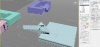
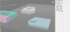
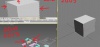
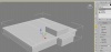
Проблема следующего характера. Сохраняю сцену в максе 2012 х86 на домашнем компе, затем открываю на работе в максе 2012 х64 и вижу сломанную геометрию объекта Edit Poly. Та же сцена дома открывается нормально (проверял уже после того, как она была изломана на рабочем компе). Аналогично ,если моделирую что-то на работе, то дома открывается безобразие. На первой картинке сломанная геометрия, на второй — как должно быть. Булевых операций тут нет, чистая Edit Poly. Объекты, выполненные экструзией из сплайнов в той же сцене отображаются нормально. Соответственно, вопрос: почему это происходит и как этого избежать?
И вдогонку еще два вопроса: Вдоль ребер объектов во вьюпорте видны черные пилообразные зубчики. Они видны и при отображении Realistic и Shaded. Сглаживание объектов отсутствует. На рендере они отображаются нормально. Проблема именно с отображением во вьюпортах. Пробовал менять Display Driver, не помогает. Точнее, если драйвером ставлю DirectX, то зубчики пропадают, потому что объекты отображаются целиком черными, а если OpenGL, то те же самые зубцы. Как от них избавиться? И второй вопрос по отображению: при включенном Edged Faces ребра должны отображаться белым (выделенные — красным). Но на объектах ребер практически не видно, изредка мелькают пунктиром и всё. Тем самым очень затрудняется работа. Такое отображение происходит на обоих компах, хотя видеокарты совершенно разные: дома ноут с ATI Radeon, на работе ПК с NVidia.
-

574,5 КБ
Просмотров: 1 422 -
469,2 КБ
Просмотров: 1 174
А максы то вылечены?»Зубчики» это не совсем корректная работа драйвера Nitrous.Что делать !? Переключиться на «директ» .
Вылечены — это как?
С зубчиками разобрался — Viewport Clipping, а насчет директа я писал, что в нем все объекты отображаются полностью черными, так работать невозможно.
В смысле, установлены hotfix(ы)-заплатки с оф.сайта исправляющие проблемы макса.
Не пробовать нужно а ставить.И ставить не всё подряд а то,что действительно необходимо.Читай инструкции(обязательно!!!).
Установил хотфиксы, не помогло. Причем во вновь созданной сцене те же ошибки, геометрия ломается. Сначала думал, что ошибки геометрии только в координатах вершин, но сейчас вижу, что и кол-во вершин у одного и того же объекта разное.
Установленные хотфиксы:
Autodesk 3ds Max Design 2012 Service Pack 2
Autodesk 3ds Max Design 2012 Product Update 12
Composite 2012 Hotfix не установился — написал, что он уже есть.
UPD: Экспортировал в 3DS — сцена открывается нормально, геометрия в порядке. Но как то это напряжно, постоянный импорт-экспорт.
UPD2: Проблема возникает именно с Edit Poly (когда в стеке модификаторов присутствуют предыдущие модификаторы). Если схлопнуть весь стек в Editing Poly, то проблема исчезает. Видимо придется так и делать, главное не забывать схлопывать, я привык работать с развернутым стеком, если модель простая.
Я надеюсь «перезагрузиться» не забыл?!Если не помогло скинь файл.
Днем к сожалению не смог проверить. Ошибка осталась.
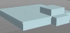
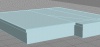
На первой картинке то, как оно выглядит в 3ds max design 2012 x64 (у модели 54 вертекса), на второй — в 3ds max design 2012 x86 (49 вертексов). Модель выкладываю.
Ссылка на молель http://yadi.sk/d/7lRU-Kqy3ozEw
-
102 КБ
Просмотров: 932 -
69,7 КБ
Просмотров: 713
Уникальный случай.Файлы действуют на отображение объектов в сцене.На изображении 3 макса 2012, 2014(13) и 2009.При том только с этими файлами .Будем разбираться.
-
245,9 КБ
Просмотров: 774
А дай мне такой покрутить,..
уже не в первый раз встречаю такую проблему у людей, а у себя ещё не было.
На вскидку, по отображению, похоже проблемы связанны с масштабом сцены как только уменьшил(Scale) артефакты исчезли.Складывается ощущение,что был произведён не совсем корректный импорт.
Проблема не в отображении. Отображение лечится юзаньем Viewport Clipping (см. пост 3). Проблема в том, что сами модели разные в разных максах (пост 10).
Viewport Clipping везде отключён.(рис1).Сцена открыта максе 2012 х64 без ошибок(рис2).
-
97,8 КБ
Просмотров: 634 -
276,8 КБ
Просмотров: 628

В 2012 х64 у меня тоже без ошибок открывается. Но в х86 с ошибками. Есть возможность проверить на 32-разрядной винде?
Нет.Возможно у ребят есть. Попробуй ещё через формат FBX.
В FBX и 3DS сохраняет нормально, но постоянный импорт-экспорт напрягает.
Для меня вообще удивительным считается сам факт открытия файла (созданного в 64 программе) в 32 битном максе. Обычно пишет ошибку.
Экспорт выделения. Если выделение какого либо элемента нужно сохранить, но трансформации требуется подвергнуть другой подобъект (находящийся в области выделения), то вы всегда можете перемещаться по списку. Достаточно в перечне кликнуть по интересующему разделу с нажатым Ctrl.
Если удерживать Ctrl+Shift, то на следующий уровень вы сможете перенести все за исключением границы.
Ignore Backfacing запрещает выделение рамкой элементов, которые не видны нам в данный момент (находятся с обратной стороны объекта).
By Angle (по углу). Тонкий инструмент. Удобен при достаточно сложной топологии поверхности объекта. С его помощью можно выделять элементы, которые соединены под определенным углом относительно друг друга.
Стоит отметить, что теоретическое знание модификатора Edit Poly 3D Max не гарантирует высокого уровня моделирования, поэтому стоит начинать изучение программы с
бесплатного курса
, чтобы понять, это ваше или нет. Огромную роль играет практика. 3ds Max достаточно сложная программа, в которой решение задачи доступно множеством способов. Только опыт поможет определить наиболее рациональный из них. Также важно представлять, каким образом реальные объекты могут быть описаны при помощи полигонов. Это умение тоже зависит от практического опыта. Неважно, сколько вы прочтете или посмотрите уроков. Профессионалом они вас не сделают. Теоретическая подготовка важна, но без самостоятельной практики, поиска решения задач, экспериментов – она бесполезна. Не отчаивайтесь, если создание простых моделей на начальных этапах у вас занимает массу времени. Через некоторое время ваши навыки значительно улучшатся, если проявить упорство и терпение.

Иван Юриков
Визуализатор. Преподаватель AMS³
3Ds Max
Искажения на мебели в 3ds Max
Очень часто на визуализациях можно встретить искажения корпусной мебели. Это некорректная работа инструментов Smoothing Group и Chamfer. Более подробно группы сглаживания разобраны в статье Сглаживание с помощью Smoothing Groups в 3ds Max. В текущей статье мы разберем только способы исправления ошибок.
Курс «Моделинг мебели в 3ds Max»
Марафон 3ds Max «Визуализация интерьера»
При создании фаски, на модель автоматически добавляются группы сглаживания. Но добавляются они некорректно. Визуально фасады становятся «пухлыми». Эту проблему легко заметить на этапе моделирования. Просто покрутитесь вокруг модели после добавления фасок. Если увидите подобный резкий переход между светом и тенью, значит модель исказилась.

Как исправить искажения?
1. Настройка Chamfer
Удобнее всего убирать группы сглаживания внутри модификатора Chamfer. Но для этого нужно работать именно с модификатором. Одноименный инструмент в Editable Poly не подойдет, в нем нет нужных настроек.
Опустимся вниз и в разделе Smoothing Output поставим режим Smooth Chamfers Only. После этого искажения пропадут.

Также обязательно ставьте галочку Smooth to Adjacent. Без нее плоская часть фасада будет иметь жесткие ребра рядом с фасками. Установка галочки сглаживает переход и сохраняет ровную форму фасада.

Хотите научиться моделировать мебель и зарабатывать на этом? Пройдите курс «Моделирование мебели в 3ds Max». Курс рассчитан на тех, кто начинает с нуля. Спустя несколько недель обучения вы сможете смоделировать любой предмет интерьера. Подробнее о курсе смотрите тут.
2. Скрипт IFWN
Этот скрипт убирает искажения от сглаживания на любых объектах. Допустим, Вы конвертировали объект в Editable Poly, а сглаживание поправить забыли. Или Вам просто не нравится автоматическое сглаживание в 3ds Max.
Ссылка на скрипт http://www.scriptspot.com/3ds-max/scripts/improved-face-weighted-normals
«Инструкция по использованию скрипта IFWN»
- Выделяем целевой объект;
- Запускаем скрипт;
- Нажимаем Generate.

На модель добавится соответствующий модификатор и отобразит, как теперь выглядят нормали. Плоскость фасада стала чистой. Переход между плоскостью и фаской гладкий.

Хотите стать автором и зарабатывать на этом? Напишите нам.
Стать автором
Начни учиться бесплатно
Зарегистрируйся в AMS3 и получи бесплатный доступ к интенсивам, курсам, коллекциям блоков, семейств, моделей и текстур
Начать обучение
Статьи и уроки по этой теме